

Auxbeam’s RA80 X2 Dual Panel Switch System In A Camping/Overland Vehicle
Auxbeam’s RA80 X2 8-gang dual switch panel system can be very useful for a vehicle configured for camping and overlanding - one switch panel can go within the driver's reach for accessories like driving lights, and the second panel can go in the back to be easily accessible at the campsite. (https://auxbeam.com/products/qp009818).


Using dual panels to control driving and campsite accessories does bring up additional wiring considerations. Normally, the system would be powered by a switched circuit in the vehicle and therefore only powered when the ignition is switched on, but it is not a good idea to require the ignition to be switched on whenever accessories controlled by the switch panel need to be used at the campsite - at best, it's inconvenient and at worst leaving the ignition switched on at the campsite could result in the battery being drained. This article will cover wiring considerations and some installation details for a typical camping/overland vehicle to avoid unnecessary battery drain at the campsite.
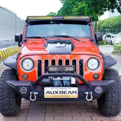
The vehicle being used in this article is a 2013 Jeep Wrangler Unlimited. In front it has Auxbeam driving lights mounted on the roof rack and in the cargo area a MORryde Trail Kitchen are installed. One of the switch panels will be mounted up front near the driver and the second will be mounted in the back by the Trail Kitchen.
The first thing to know in planning your installation is that the two switch panels work in parallel - there are 8 circuits in the RA80 X2 control box and each panel has 8 switches. Switch 1 on both panels controls circuit 1 in the control box, so if driving lights are connected to circuit 1, switch 1 on either panel with operating those lights. You have 8 circuits for accessories, and all of those 8 circuits can be controlled from either panel.
Powering The RA80 X2 Control Box
With a typical single switch panel system, it is normally recommended that the control box be powered by a switched circuit in the vehicle. A switched circuit is one that's powered on when the ignition switch is in the on position, and powered off when the ignition switch is off. Powering the panel with a switched circuit ensures that the switch system and its connected accessories won't drain the battery when the vehicle isn't running.
Considerations may be different for a dual switch panel system - if the second panel is mounted in the back of the vehicle for use at the campsite, for example to control campsite lights mounted to the roof rack, you wouldn't want to have the ignition switch on all the time at the campsite - you'd want the switch system to operate without the ignition switch having to be on. Let's review three wiring options...
Wiring Option 1 - Switched Circuit In Vehicle (Per Auxbeam Instructions)
The instructions recommend powering the control box from a switched circuit in the vehicle, which means that any accessories connected to the system will only be able to operate when the vehicle is running or the ignition switch is turned on. For accessories used when driving, like driving lights, that's not a problem, because the switched circuit will be on.
But if the second switch panel is used in the back of the vehicle to control campsite accessories, you would either have to have the vehicle running or have the ignition switch turned on at the campsite for those accessories to be used. Running the engine all the time probably isn't a good idea, and having the ignition switch turned on all the time at the campsite isn't the best idea either - the vehicle circuits that are powered when the ignition switch is will be an unnecessary drain on the battery and could lead to a discharged battery overnight.
Wiring Option 2 - Driving/Campsite Switch
A way to use the switch system with the ignition switched off is to install a switch to control the power to the control box. In the "driving" position, the switch would power the control box from a switched circuit and in the "campsite" position, the switch would power the control box from an unswitched circuit. What’s good about this is for normal driving, any accessories controlled by the system will be powered off when the vehicle is not running, so they can’t be left on accidentally and drain the battery. And at the camp site, accessories can be used without the need for the ignition switch to be on.

The switch is a single pole double throw (SPDT). Optionally it could be an SPDT Center Off switch, in which case the center position would cut all power to the control box off.
The benefit of using the switch system in "campsite mode" is that the vehicle circuits that are powered by the ignition switch being in the on position will not be powered, which eliminates some drain on the battery while sitting at the campsite. Typically, you wouldn't be using "driving accessories" at the campsite such as driving lights, you would only be using campsite accessories, perhaps LED campsite lights mounted to the roof rack, so power drain would be limited to just the campsite accessories plus the small power draw that the switch control box requires.
But forgetting to turn off campsite mode when you no longer need it could cause your vehicle battery to discharge, so it might be a good idea to have a reminder that the campsite mode is on. This can be done with a double pole double throw (DPDT) switch and a 12v LED indicator light; wired as per the next diagram, the LED will light whenever campsite mode is on and will serve as a reminder to turn off campsite mode when it is no longer needed.

The switch control box draws about 75MA. With both switch panels connected and all circuits turned on. That's a negligible drain on the main vehicle battery just for the control box, but to that the drain of the accessories switched on must be added. For example, if an accessory that draws 10 amps is to be switched on, it may not be a good idea to power that from the main vehicle battery when the vehicle isn't running - it may drain the battery past the point of being able to start the vehicle the next morning. Which leads us to the third option...
Wiring Option 3 - Vehicle With Two Batteries
Our test Wrangler has two batteries - the standard vehicle battery up front, and a fridge/kitchen battery in the back. In this vehicle, we'll use the driving/campsite switch described above to power the switch control box, but the campsite accessories in the back can be powered either from the main vehicle battery or from the kitchen battery. Powering campsite accessories from the kitchen battery will greatly reduce the load on the main vehicle battery, ensuring that the main battery will have enough power to start the vehicle when it’s time to leave the campsite. More on this wiring later.
The test Wrangler has a refrigerator in the back that’s powered from the fridge/kitchen battery. Since the fridge typically is used from the moment food is loaded before an expedition until returning home, there’s no real need to control its power using the switch panels. The kitchen battery is mounted in the back right next to the fridge, and the fridge has a convenient power switch on its front panel, so it’s directly connected to the kitchen battery. Only accessories which will be turned on/turned off at the campsite will be controlled through the switch panel system.
Mounting The RA80 X2 Control Box
Modern engine bays are very cramped and often don’t provide many good locations for mounting things like the Auxbeam control box. In our test 2013 Wrangler, there are several possible locations. The best location is probably to the inner fender on the driver’s side – the supplied angle bracket mount can be bolted to the inner fender (left photo). Drilling the inner fender is required. The drawback of using this mounting location is that the supplied battery cables are too short to reach from this location to the battery.

There are two mounting options on the passenger - mounting the box to the top of the TIPM (Jeep’s name in the underhood fuse/electronics box, left photo below), or to the top of the air filter housing (right photo). The supplied battery cables will reach to both of those locations. If you do decide to install in either of these locations, be sure to provide enough slack in your accessory wiring to be able to open the TIPM or the air filter housing when needed.

Routing Wires To The Back Of The Vehicle
For this installation four of the circuits are going to be dedicated to driving accessories and four to campsite accessories. The second switch panel will be mounted in the back of the Jeep, and with power accessories back there a four-conductor wire will be run along with the switch panel wire. 16/18-gauge 4-conductor trailer wire will be used and protected along with the switch panel cable in 3/8” diameter split wire loom to make routing the wires easier and more professional looking. The switch panel cable and the 4-conductor cable both fit nicely in the wiring loom:

One of the wires will be for each of the four circuits dedicated to the rear accessories, and ground connections will be made to the Jeep body in the back. Optionally a separate large gauge ground wire could be run from the back of the vehicle with the battery in the engine bay for a better ground connection - accessories in the back would be grounded that wire.
The four-conductor trailer wire is adequate for most low-power devices such as LED lights, but higher-powered accessories will likely require larger gauge wire to be run. In the case of this Jeep, however, this gauge wire will be adequate because higher power accessories in the back will be run from the kitchen battery, and the smaller gauge wire will control a relay to switch the kitchen battery power to that accessory as per option 3 above.
The control cables from both switch panels and the wiring for the accessories out back will need to be routed out of the engine bay and into the interior of the vehicle. Other vehicles will be different; what follows is one way to do it in a JK Wrangler. The JK has a large hole in the firewall just behind the battery, its location is marked by the yellow square in the left photo below. To access this hole, pull the plastic cable straps (arrows) off the studs in the firewall and pull back the cable and the firewall insulation. The hole is covered with a piece of soft black self-stick plastic that can be peeled back.

Once the insulation and self-stick plastic are out of the way, cut a hole in the insulation on the inside of the firewall that’s big enough to push the wires through. The insulation backs with plastic, so you’ll need to cut a hole through the plastic. When the hole is large enough, push the wire through from the engine bay side; when enough has been pushed through, you can reach under the dash and pull it through from that side. Pull the wire through until most of the wire is inside the Jeep.
Once the wire is inside the Jeep, the control cable from the front switch panel can be routed under the dash to wherever you plan to mount that panel, and the control cable and wires for the rear can be routed under the carpet alongside the door openings
Mounting The RA80 X2 Switch Panels
Switch panels can be mounted up front using a phone/GPS clip mount. These can be a good choice for mounting near the driver because modern vehicles don’t offer much empty dash real estate and using these types of mounts, the panel can be installed in several places, usually without drilling.

A great place to mount the switch panel in the rear of a Wrangler is on the roll bar. This uses the supplied mounting bar and it’s held to the roll bar with zip ties. In the rear of the Wrangler the panel can also be mounted on the inner fender trim panel (right photo). It’s mounted using double-sided tape to avoid the need to drill holes in the trim panel.

Powering Accessories On The Back
The four wires that were run from the control box up front to the rear of the vehicle can directly control accessories in the back – for example the campsite lights installed on the roof rack can be connected to one of those wires and they’ll be controlled from the circuit that wire is connected to in the control box, and powered from the main vehicle battery.
Since the test vehicle for this article has a kitchen battery in the rear, accessories can optionally be powered from that battery, which is a good idea for campsite accessories – powering those from the kitchen battery will reduce the load on the main vehicle battery. As much as possible and practical, it’s a good idea to reduce the load on the main battery while at the campsite – we don’t want the main battery to discharge to the point where it won’t start the vehicle when it’s time to leave the campsite.
Powering an accessory from the kitchen battery is accomplished with a relay:

The green wire is one of those routed from a circuit in the control box in the engine bay and it powers the relay when that circuit is switched on. The red wire goes to the positive terminal of the kitchen battery, and through the relay the kitchen battery powers the accessory, in this case a campsite light. The relay is mounted in the back, near the kitchen battery.
The relay in the diagram above is a standard Bosch type automotive relay. These draw about 175MA. When activated, which isn’t much, but there are relays that draw about 20MA. When activated, and solid-state relays that draw 5ma., so if you’re really trying to minimize drain on the main battery, lower-power relays are available. But 175MA isn’t much to worry about.
Additional Features
The main focus of this article is wired to minimize power drain in an overland/camping vehicle, so this article won’t cover some of the additional features of the switch system in detail. Special features include the ability to change the color of the switch panel backlight (perhaps to match the color of your dash lights), and the ability to set the mode of each switch.
The default mode for each switch is on/off - one press turns the circuit on and a second press turns it off, but switches also can be set for momentary operation (circuit is on only while the switch is pressed) and pulsed mode - one press turns on the circuit, which will blink the output, and a second press turns it off. Pulsed mode can turn a light into a flasher, which may be useful for first responders. Those switch modes are demonstrated in this video:

Auxbeam supplies two identical sets of 60 stick-on labels for the switches (one set for each switch panel) and there’s a pretty good selection:

They also offer a set of 120 additional stickers that include more labels and graphics (https://auxbeam.com/products/qp009375) so if you don’t find what you need check those out.
But if you do have accessories for which there are no labels, see Auxbeam’s web site for an article on how to make your own custom switch labels: https://auxbeam.com/blogs/how-to-choose/making-custom-switch-labels-for-your-auxbeam-switch-pane
Summary
The driving/campsite switch and optionally powering campsite accessories from a second fridge/kitchen battery can greatly reduce the load on the main vehicle battery. This can be important out in the wild; powering accessories off the main battery and/or requiring the ignition switch to be in the on position to use campsite accessories risks draining the main battery while camping; not being able to start the vehicle when it’s time to leave the wilderness isn’t a position anyone should be in, so plan your installation with your use of electrical campsite accessories carefully and enjoy being in the wild (and getting back out!).
The system is engineered and manufactured to Auxbeam’s usual high quality standards and is an excellent value for those needing the convenience of dual switch panels plus the additional capabilities that the system offers.
Taking It Further: An Ultimate Overland/Camping Electrical Implementation
This article has focused on minimizing the drain on the main vehicle battery to ensure that the vehicle can be started after days of camping. If the camping setup includes a fridge, it’s really a good idea to power that with a separate battery as described above to reduce the drain on the main vehicle battery.
Our test Wrangler includes several features not mentioned above which allow it to remain in the wild indefinitely. A solar panel is stored under the roof rack for travel, and slides out from under the rack at the campsite. It’s a 100-watt panel, which puts out 6 amps in full sun, and that’s been proven in the wild to be able to keep the kitchen battery charged with the fridge and other campsite accessories in use.

Additionally, the kitchen battery is wired so that when the vehicle is running, the alternator charges the kitchen battery, so while overlanding from one campsite to the next, if the kitchen battery isn’t fully charged when leaving the first campsite, it will be fully charged by the time the next night’s campsite is reached.
With the total wiring configuration in this vehicle, the only drain on the main battery at the campsite is the very minimal 75MA. That the control panel draws. All of the campsite accessories controlled by the switch system are powered from the kitchen battery and the kitchen battery is kept charged by the solar panel, so this Wrangler can stay “off the grid” indefinitely without worrying about electrical power.
Not every vehicle used for camping or overlanding needs the comprehensive overland electrical system that this Wrangler has, but by using the wiring techniques for the Auxbeam system that are described in this article you plan your installation to minimize the drain on the main battery while at the campsite.
Author-Jeff Scherb